| Home > Reviews > Theory > Constraint Singularities as Configuration Space Singularities | |
 | |
Constraint Singularities as Configuration Space Singularities |
|
This report continues our examination of the phenomenon of constraint singularity. We focus our attention on the fact that constraint singularities always represent singular points of the configuration space of the kinematic chain. As such they separate distinct regions of the configuration space and may allow transitions between dramatically different operation modes. All this is exemplified by a fascinating multi-operational parallel mechanism that can undergo a variety of transformations when passing through singular configurations.
1. IntroductionIn our previous reports (R004, R005) we defined the concept of constraint singularity. It occurs in a configuration of a parallel mechanism with n < 6 DOFs, where both the mechanism as a whole and the moving platform have at least n + 1 DOFs. By that definition, a constraint singularity is always an IIM-type singularity [Zlatanov et al., 1994], i.e., a configuration with increased instantaneous mobility (IIM) of the mechanism. IIM singularities are in fact the singular points of the configuration space of the mechanism. In other words, no neighbourhood of such a configuration in the configuration space is a smooth manifold. The existence of such points is usually associated with a phenomenon that can be loosely described as "branching" or "self-intersection" of the configuration space. Thus, a motion starting from an IIM configuration can end up in any one of the two (or more) "sheets" of the configuration space that meet at the singularity. The behaviours of the mechanism in the neighbouring nonsingular regions can be quite different. When the configuration space is also a constraint singularity the different adjoining regions of the configuration space can be expected to sometimes have different possible motions of the moving platform and, therefore, result in distinct modes of operation of the parallel manipulator. In the present paper we will discuss in some depth the phenomena arising in the neighbourhood of constraint singularities. This will be done using the example of a 3-DOF parallel robot that can undergo amazing transformations when passing through a constraint singularity and going from one 3-dimensional region of its configuration space to the next. 2. The Configuration Space and the Singularities of a General Closed-Loop MechanismThe configuration space (or the C-space) of a mechanism is simply the set of all possible configurations. One can think of it as the set of all feasible values of the joint parameters. For a serial kinematic chain all joint values are feasible (within the joint limits). However, if the chain contains closed loops, the possible joint values are only those that satisfy the loop closure equations. In other words, the configuration space is only a subset of the joint space. In general, this subset does not have to be a smooth manifold and may have singular points. The configuration space completely describes a kinematic chain. However, it is completely independent of both the choice of the input parameters (the actuators) and the output parameters (the space of desired end-effector poses). Hence, to describe a closed-loop mechanism completely, one needs to specify two mappings. The input map must give the values of the input parameters for every configuration, while the output map defines the values of the end-effector pose for each point in the configuration space. At a non-singular configuration, both mappings are smooth and non-singular. A mechanism singularity occurs if either there is a configuration space singularity, or else if one of the two mappings becomes singular. Note that, for a general nonredundant closed loop mechanism, we can speak of an "input-output map" only in the neighbourhood of a nonsingular point in the C-space. This most general definition of singularity was the basis of the approach to singularity analysis described in [Zlatanov, 1998]. It naturally leads to the recognition of three fundamental kinds of singularity: configuration-space, input and output singularities. Further study of the degeneracies of the associated tangent mappings leads to more detailed and comprehensive classifications [Zlatanov et al., 1994]. Using a similar approach, the three basic kinds of singularity were described in [Park and Kim, 1999]. A word of caution is needed here. The C-space, input, and output singularities should not be confused with the three popular singularity types introduced in [Gosselin and Angeles, 1990], although for some cases they may be the same. Herein, we will be interested mostly in configuration space singularities and to a smaller extent in output singularities. We will be concerned mainly with mechanism properties that are determined by the geometry of the kinematic chain and the choice of the end-effector, but do not depend on the choice of actuators. 3. Constraint and C-Space Singularities as Branching PointsPossibly the simplest interesting example of a C-space singularity is a flattened four-bar linkage. When all four links have different lengths, the configuration space is homeomorphic to the figure eight, i.e., from a topological point of view, it may be described as two circles joined by a single common point. That point is the C-space singularity and in its vicinity the configuration space is not a smooth manifold. Yet, one can still define a meaningful "tangent space" at this point, only this will be a linear space with two rather than one dimensions. The increased dimension reflects the fact that the configuration is an IIM singularity and the four-bar has a transitory mobility of two. Thus, the configuration space of the flat four-bar has two one-dimensional parts, and the mechanism can switch from one to the other only by passing through the IIM configuration. This is why Hunt [Hunt, 1978] refers to such singularities as uncertainty configurations.
For a four-bar mechanism (Fig. 1), the two regions of the configuration space can be easily differentiated by the orientation of the left rotor (the usual input link). In one region the moving end of this link will be above the line of the base, in the other it will be bellow. Since in the shown chain the link is a rocker, the only transition point is the singularity in Fig. 1(b). As it was pointed out in the previous paper, the situation in Fig. 1(b) can be viewed as a constraint singularity if the output link is the coupler. The constraint singularity divides the C-space into two non-intersecting non-singular regions, each being an open and connected set as well as a smooth one-dimensional manifold. The two regions correspond to two different sets of poses of the coupler. However, in every non-singular point of the C-space, regardless of the region, the instantaneous motion will be of the same type: a rotation about an instantaneous rotation axis. In other words the screw system of the output twists is always the same. Things become different when all four links have the same length (Fig. 2). In this case, there are three C-space singularities, which are also constraint singularities since in each one the coupler has two instantaneous DOFs. The three points divide the configuration space into six non-singular regions. At each C-space singularity four regions meet. In fact, the C-space is composed of three smooth closed curves in the joint space. Each curve contains two C-singular points, which divide it into two regions. Every two of the three curves have a common C-singular point and at each of the C-singularities exactly two curves meet. In the case of a four-bar the C-space can be easily illustrated since it has a faithful projection on a two-dimensional torus. Indeed, every configuration can be determined in a unique way by the value of the angles of the two base joints. Fig. 3 shows this projection. The torus is the space of all values of the two rotor angles, the (green, red and blue) curves on the torus form the feasible combinations of the two angles for which there exists a (unique) configuration.
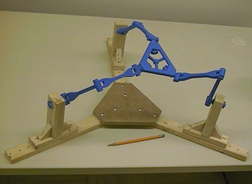
Unlike the more general flat four-bar in Fig. 1, here two distinct regions of the configuration space may allow completely different coupler motions. While on (the green) one of the three curves (i.e., in two of the C-space regions) the coupler remains parallel to the base, on each of the other two curves (four C-space regions) the coupler rotates about a point fixed in the base. At two of the three constraint singularities the mechanism has the options of entering two translational and two rotational regions, while at the third C-space singularity the four-bar can choose among four rotational regions. We could say that the mechanism can be used both as a translational and as a rotational device and the transition between the two modes of operation may occur when the device goes through a constraint singularity. It turns out that such "multi-functionality" can be observed in much more complex devices, and the transformations between different modes are quite fascinating. 4. The 3-DOF 3-URU Double-Y Multi-Operational (DYMO) Parallel MechanismConsider the mechanism shown in Fig. 4. It is a parallel device with three 5R or, more precisely, URU legs. The centres of the three U-joints at the base form an equilateral triangle. The same applies for the three U-joints at the platform. The three R-joint axes fixed in the base meet in the centre of the base triangle (in a "Y" shape) and the same is true for the platform R-joints and the moving triangle. The three intermediate R joints in each leg are all parallel. A plastic model of the mechanism was built to facilitate its analysis.
If our readers find this design vaguely familiar, they are not mistaken. In essence, it is the same as the design of the malfunctioning positioning device built at Seoul National University (SNU), the manipulator at the origin of our exploration of constraint singularities. There have been some modifications. Firstly, the prismatic joints of the SNU robot were replaced by R joints, a kinematically non-essential change of little practical importance. Secondly, the new design allows the platform triangle to be lowered in and through the base plane, a change that has no kinematic value whatsoever, but is quite important in view of the new tricks that this old design will be asked to perform. In view of this slightly modified design and the newly discovered properties, we will refer to the new manipulator as the 3-URU Double-Y Multi-Operational (DYMO) parallel mechanism. We will assume that the two parts of each leg (i.e., the two links in the leg chain with non-zero length) are close but different in length. We will also assume that they are quite long, and we will not concern ourselves too much with the configurations where a leg becomes fully stretched or folded. We will also ignore the effects of link interference. Our interest is in the structure of the configuration space and the nature of the end-effector motion rather than the workspace limits.
We will now proceed to study the configuration space of the kinematic chain in a way similar to the analysis of the folding four-bar in Section 3. The goal is to identify the C-space singularities and the non-singular C-space regions. Moreover, we want to know whether the C-space singularities are also constraint singularities and what end-effector motions are possible in each non-singular region. Furthermore, it is of interest to study the possibilities and forms of transition between the C-space regions. It turns out that there are several distinct modes of operation of this parallel chain with completely different motion capabilities of the platform. 5. A Translational Manipulator – or TwoSince the original design was conceived as a positioning mechanism it is no surprise that the mechanism can be translational in part of its configuration space (Fig. 5). Translational mechanisms of this type (with two U-joints in each leg) were proposed by Tsai [1996]. Their singularities, including constraint (in this case, rotational) singularities were studied by Di Gregorio and Parenti-Castelli [1999].
Let the base and platform have the same orientation, and neither of the legs be singular, i.e., the five R-joints in each legs are linearly independent. Then, the constraint imposed by each leg on the platform, i.e., the wrench reciprocal to all the leg R-joints, is a pure moment, perpendicular to all five of the R-joints. The three constraints will remain linearly independent unless one of two things happens: (a) the platform centre is right above the base centre; or (b) the platform triangle is lowered in the base plane. The intersection of these two singularity sets should be considered separately as case (c) where the platform centre is at the base centre (as in Fig. 4). We can conclude that once the mechanism is assembled with zero platform orientation it can move only as a positioning device until it reaches one of the configurations defined by conditions (a) or (b). Case (a) corresponds to the constraint singularity described in our first report. This is an IIM configuration where both the kinematic chain as a whole and the moving platform have five instantaneous DOFs. Some of the allowed twists are all translations, as well as all rotations with horizontal axes. When the platform is in the base plane, case (b), the three constraint moments become coplanar and the platform acquires the capability to rotate about any vertical axis. The mechanism as well as the platform will generally have 4 DOFs. If the platform centre is lowered in a base-plane point lying on one axis of a base R-joint, then the mechanism will still have 4 DOFs but the platform will lose one freedom and will have only three instantaneous DOFs. Indeed, when the platform centre is on the base "Y" (formed by the base R axes), but not in the base centre, there is a single continuum of configurations with a fixed platform because of the spin of one of the legs. However, only one of those configurations, where all three legs lie in the base plane, is a C-space singularity. In this case the mechanism has 4 DOFs but the platform only three, two horizontal translations and a vertical rotation. Finally, it is important to note that case (c), when the platform and base centres coincide, corresponds to infinitely many translation-mode configurations. The reason is that each of the legs can spin along its axis while base and platform coincide. However, not all of those configurations, forming a 3-dimensional torus, are adjacent to translation-mode regions. These points form a 2-dimensional surface on the 3-dimensional torus. This situation is further addressed in Section 8. Note that there are C-space singularities, of cases (b) and (c), for all positions of the platform centre in the base plane. Yet, these configurations do not divide the set of non-singular zero-orientation translation-mode configurations into two. There exist paths that avoid C-space singularities and join any two configurations on both sides of the base plane. For such paths, the platform centre passes through the base plane in a point along the base "Y" (but not the base centre). As we pointed out above, such configurations are not C-space singularities as long as the single singular leg is not in the base plane. Moreover, note that each such configuration has a neighbourhood of non-singular C-space points. Hence, the non-singular C-points with zero platform orientation form a connected open set. It is now time to observe that everything written since the beginning of the present section is valid if "zero orientation" is replaced with a "180-degree-yaw orientation". Hence, there are two translation-mode regions. Clearly, the two translation modes (with different orientations) cannot have common boundary points but, as we will see later, this does not mean that there are no configuration space paths between the two. 6. An Orientational ManipulatorIn our previous paper (see Fig. 1 in that paper) we used the example of a parallel wrist with three UPU legs first proposed in [Karouia and Hervé, 2000]. The constraint singularities (in this case, translation singularities) were first reported by Di Gregorio [2001]. The link-geometry condition is that the base R joints intersect in a common point and so do the platform R joints. This condition is satisfied by the DYMO chain as well and therefore it has an orientation mode of operation (Fig. 6).
Assume that the base and platform centres coincide and no leg is singular (i.e., no platform R joint is aligned with the corresponding base R joint), as is the case in Fig. 6. Then, the unique constraint wrench of each leg is a force through the common centre and parallel to the intermediate R joints of the leg. When the three forces are linearly independent, the system of the platform twists will be the 3-system of all rotations about the centre. When the three constraint forces become coplanar the platform acquires the freedom to translate in a direction orthogonal to the plane of the constraints. Such a configuration will then be a C-space and a constraint singularity since the platform will have at least 4 DOFs (if all three forces are parallel, which can happen only if the platform is horizontal, the platform acquires two horizontal translations for a total of 5 DOFs). We will now consider the configurations where a leg becomes singular and its base and platform R-joints align. This adds one more leg constraint: a pure moment perpendicular to the plane of the U joints. This constraint reduces by one the freedoms of the platform, and then the end-effector may remain with 3 DOFs, even when the constraint forces are coplanar. However, the configuration is still an IIM singularity, because now there is an extra mechanism freedom not involving the platform. Indeed, the singular leg can freely spin about the aligned revolute axes even when the platform is fixed. Either exactly one or all three legs can become singular when the centres coincide. In the first case, the platform always has exactly two rotational freedoms. If the constraint forces are coplanar (which can be arranged for any of the considered platform orientations by spinning the singular leg) then the platform can translate as well. The platform has three DOFs and the mechanism four. When all three legs are aligned (i.e., the platform has zero or 180-degree-yaw orientation), each leg imposes two constraints – a force and a moment. The configuration is adjacent to an orientation-mode region only if some rotations are allowed, i.e. if the three moment vectors are coplanar. If this is the case, then the mechanism as a whole will have at least 4 DOFs because of the spinning of the three legs, hence we have an IIM (C-space) singularity. We can conclude that the C-space singularities adjacent to the orientation mode are exactly all those configurations (with coinciding centres) where the lines defined by the intermediate R joints are parallel to the same plane. It can be shown that these configurations all have an orientation of the platform with zero yaw, i.e., they are obtained from the zero orientation by a single (finite) rotation with a horizontal axis (a tilt in the vertical plane of some azimuth). All such orientations correspond to C-space singularities. However, if the axis of the finite (non-zero) tilt is one of the base R-joint axes, then there are infinitely many configurations (due to leg spinning) and not all of them lead to coplanar constraint forces and C-space singularities. Only one of the orientations of the spinning leg (for every half-turn) corresponds to a constraint singularity, while for any other the chain is in a non-singular C-space point. The problem of the identification and description of the platform orientations corresponding to constraint singularities in the orientation mode was solved by using the so-called modified Euler angles as introduced in [Bonev and Ryu, 1999].
This formulation allowed for particularly simple final expressions and also made it easy to establish that the IIM singularities divide the set of non-singular orientations of the platform into two connected components (with positive and negative yaw angle, respectively). However, this does not mean that the surface of C-space singularities also divides the set of non-singular configurations in the orientation mode. The situation is a close analogy to the translation mode and the role played by the configurations with platform centre in the base plane. In orientation mode as in translation mode, there are non-singular C-space paths that can pass through the singularity surface. These paths cross from positive to negative yaw through any configuration where the tilt axis is one of the base R-joints. Moreover, as was the case with each of the two translation modes, the non-singular orientaiton-mode C-space points form a connected open set. The existence of the orientation mode answers one transition question from the previous section. Assuming that the leg length is sufficient, it is possible to move continuously between two translation-mode configurations with opposite yaw angles. The path can go through the orientation mode, where it can enter with zero orientation and exit with a horizontal platform and a yaw of 180°. We will see later that this is not the only route between the two translation modes. 7. Two Mechanisms for Planar MotionWhen analyzing the translation mode in Section 5 it was mentioned that the platform can be lowered into the base where it will acquire as a fourth DOF a vertical-axis rotation. In Section 6, it was mentioned that if all three constraint forces are vertical, while the mechanism is in orientation mode, then the platform acquires two horizontal translations. In both cases the system of the possible platform twists includes as a subsystem the planar motions. It is not difficult to see that the ability for planar motion is not transitory and that finite planar motions can originate from the described configurations. Indeed one glance at the mechanism should be sufficient to immediately recognize the features of a 3-RRR planar parallel manipulator (Fig. 8).
Let the platform be in the base plane (with arbitrary orientation). If no base and platform R-joint pair is aligned (and there can be no leg spinning) then all intermediate R-joints must have vertical axes or, in other words, all legs lie in the base plane as well as the platform. If no leg is singular, the unique leg constraint will always be either a vertical force or a horizontal moment. Therefore, the planar motions will always be allowed and this will be a planar mode of operation of the mechanism. It must be observed that the above is true not only when the platform is in the base plane "face up" but also "face down", although then the 3-RRR planar parallel mechanism will be less recognizable since the base and platform attachment points will be in reverse circular order. Also, the leg length must be larger than in the shown model and there will be link interference. So there are two planar modes, which obviously do not have common adjacent configurations, yet it is still possible to go with a continuous motion from one to the other via the orientation mode. We will see later that there is another route as well. We now identify the C-space singularities adjacent to the planar modes. The picture in the "face-down" is quite different from "face up". This is unlike the situation with the two translation modes where there was complete symmetry and all singularities for the two fixed orientations were essentially the same. In any mode of operation, when a leg is nonsingular the unique leg constraint is either: a force parallel to the intermediate R-joint axes and passing through the intersection of the base and platform R-joints; or, if the base and platform R-joints are parallel, a moment perpendicular to the U-joints plane. In planar mode, a constraint singularity will occur when either: (a) the three vertical constraint forces are applied on a common line in the base plane; (b) the three constraints are horizontal moments; (c) one of the constraints is a moment and the other two are forces whose plane is perpendicular to the moment. (Note that if two constraints of two legs are moments then the third leg must have parallel base and platform joints). First we consider "face-up". Here only case (b) is possible. Hence the C-space singularities must be among the configurations with zero or 180° orientation of the platform. When no legs have aligned 1st and 5th joints, the platform has 4 DOFs, adding the vertical translation to the planar freedoms (Fig. 9). When for one leg the platform vertex is on the base R-joint axis, the mechanism has four DOFs but the platform has only the three planar freedoms. When all three legs have their first and last joints on the same line, i.e., when the platform is at the centre with an orientation of 0° or 180°, the mechanism has 6 DOFs, but the platform can still move only with the three planar DOFs. All of those singular C-space points are boundary points to a translation region. The central configuration is adjacent to the orientation mode as well. The C-space singularities divide the "face-up" planar mode into two regions (with positive or negative orientation angle).
If the platform is face-down, only cases (a) and (c) can occur. It can be shown that these singularities correspond to the following platform planar poses. For every orientation of the platform the singular locations of the platform centre are given by a pair of perpendicular lines through the origin. The orientation of this pair of lines changes with the orientation of the platform, only twice slower. The singularity surface formed by these rotating lines divides the face-down planar mode into four component regions. The singularities in type (c) are those obtained when the platform orientation is such that one of the platform joints is either along or orthogonal to the base joint in the same leg. In both the (a) and (c) singularities the platform acquires a non-planar rotation about a horizontal axis. This axis is along the line defined by the application points of the constraint forces. In case (a) the mechanism has 4 DOFs and so does the platform, in case (c) the platform has still 4 DOFs but the mechanism has 5. We should note that when the platform centre is not at the base centre, the constraint singularities of the face down mode do not border on either the translational or the orientation mode. They allow the mechanism to escape into another mode of operation which will be described later. 8. Two Lockup Poses Each With Three DOFsLet us consider the case when the base and platform centres coincide and the platform orientation is either zero (Fig. 10) or with a yaw of 180° and the platform is horizontal and face up (zero azimuth, zero tilt).
Since all legs can spin independently, there is a 3-torus of such configuration for each of the two platform orientation. For most points of the torus the mechanism has 3 DOFs but the platform cannot move, in other words we have a triple infinity of dead-point configurations where the platform is "stuck". It is convenient to view this as a separate "mode of operation". In this mode, there are C-space singularities where the platform acquires a freedom and can escape the lockup pose. Each leg imposes two constraints, a force and a moment. There are two types of IIM singularities: (a) when the three moments are co-planar and (b) when the forces are coplanar. In case (a) the platform can escape with a rotation about the common centre and enter the orientation mode, while in case (b) the platform can translate and enter the corresponding translation mode. There are singularities which satisfy both conditions (a) and (b). For example, when all three legs lie in the base plane, the platform has 3 DOFs and it can escape with any planar motion. Another example is the nexus configuration with coinciding base and platform (Fig. 4) and horizontal U-joint planes. Now all legs are singular and each imposes two constraints (a force and a moment). However, the moment, in the vertical direction, is the same for all legs, while all three forces are horizontal. The resulting constraint system consists of all forces in the base plane and the vertical moment. This is a self-reciprocal 3-system and hence the system of the platform freedoms is spanned by two non-parallel rotations in the base plane and a vertical translation. This configuration is on the border of both the translation and orientation regions. It is also adjacent to the mode described in the following section. 9. A New Parallel Manipulator With Three Mixed FreedomsAt several occasions in the preceding discussion we described singular C-space points from which the kinematic chain can enter a new mode of operation where the platform is neither parallel to the base nor with a fixed point. This is in fact a fourth type of operational mode with 3 output DOFs (apart from the translational, orientational and planar modes). In this mode, the mechanism operates as a new (or at least previously unknown to the authors) manipulator with three mixed freedoms. Consider for example the configurations where the platform centre is right above (or below) the base centre and the platform is parallel to the base and yawed at an angle of 0° or 180°. From these IIM configurations the mechanism can exit into the translation modes using three of its five instantaneous freedoms. Can it exit while using the two rotational freedoms? Or consider the singularity in orientation mode where the platform plane is not parallel to the base and yet the mechanism acquires an instantaneous translation. Can it exit the orientation mode along this translation? The answer to both of the above questions is affirmative as can be seen on Fig. 10. Once the possibility is recognized it is easy to find configurations of the mechanism where the two centres are distinct and the base and platform are not parallel.
To find the set of all these configurations we can start by looking at the possible instantaneous motions at one such configuration. Assuming that no leg is singular and that the base and platform intersect, the leg constraint wrench is either: a force passing through the intersection point of the base and platform R-joint axes and orthogonal to the plane of the leg; or, if the latter axes are parallel (they cannot be skew since they are both in the leg plane), a moment orthogonal to the plane of the leg joints. This implies that if a constraint is a force it must be orthogonal to the line connecting the base and platform centres since this line lies in all leg planes.
Conversely, all configurations in the mixed mode can be obtained starting from an orientation-mode constraint singularity by translation along the exit vector. We already described the singular points in the orientation mode. They are obtained with a tilt of the platform about any horizontal axis (zero yaw). We need to know the direction of the exit vector for each such singularity. It is the direction orthogonal to the common plane of the constraints and, as it it turns out, it is obtained from the vertical by exactly half of the tilt of the platform. In other words the exit vector is inclined in the same vertical plane as the platform normal and it bisects the angle between the platform normal and the central vertical axis. (This result, just as the description of the orientation-mode C-singularities, was obtained with relative ease due to a symbolic formulation using the modified Euler angles). Now we can describe the configuration set of the mixed mode. The set is axisymmetric with respect to the central vertical line. For every azimuth there are configurations with arbitrary tilt between 0° and 180°. For all configurations with a given tilt angle, the platform centres are along a ray from the origin and at half the tilt angle from the vertical axis. Thus, along the vertical axis we have configurations with tilt zero; along a ray inclined at 45° are the configurations with tilt 90°, i.e., with a vertical platform facing away from the central axis; and along a ray in the base plane we will have a tilt angle of 180°, i.e. the platform is face down and entering the face-down planar mode. This construction is performed twice, once starting with a horizontal platform with zero orientation and once starting with a platform yawed at 180° (about the platform normal). In other words for every feasible configuration of the mixed mode there is one configuration with a platform rotated at 180° about its normal axis. That may sound similar to the situation with the two translation modes. The difference is that in the mixed-mode case there are direct paths between the two regions. This is not entirely obvious, and we will try to clarify it below. But first, let us describe completely the constraint and freedom systems at each mixed-mode configuration, where the platform is not parallel to the base. We already discovered one possible platform motion, the translation along the line joining the centres, which is orthogonal to any constraint force. In addition, now that we have described the platform poses in the mixed mode, we know that the intersection line of the base and the platform is also orthogonal to the centre-joining axis. Therefore, since the constraint forces are applied in points on the intersection line, it follows that all constraint forces lie in one plane orthogonal to the line between the centres and passing through the intersection line. Furthermore, this plane must always be equidistant to base and platform, since the plane's normal is inclined at half the angle of the platform normal. Therefore, the freedom and constraint systems in a mixed-mode configuration are given by the same 4th special screw 3-system. It is composed of all zero-pitch screws in the bisecting plane and the infinite pitch screws perpendicular to it. The singular points in the mixed-mode part of the configuration space occur along the vertical axis and in the base plane. Both groups of singularities have already been described. The vertical axis contains points adjacent to the mixed and the two translation modes. The configurations in the base plane are common with the face-down planar mode. We recall from Section 6 that the constraint singularities in the face down state correspond to platform positions along rays from the origin, where every orthogonal cross of rays corresponds to a different orientation angle. These orthogonal crosses describe how the platform can enter and leave the origin face-down during mixed-mode operation. The platform can end up face down and with an arbitrary orientation angle in the base plane. For every such orientation, however, it can leave the origin only along trajectories tangent to a unique cross. Starting along one line of the cross, the platform can be tilted back up until it is face up with zero orientation. Starting along the other line of the cross, the platform will be tilted back up to a yaw-of-180° orientation. Thus, at any mixed-mode configuration, we can turn the platform around without leaving the mixed mode. We need to tilt down (and translate) until the platform is face down and at the base centre; next (translate and) tilt up 180° in the orthogonal direction, until we are face up; and finally, tilt down to the original position, now with the platform rotated half-turn about its normal axis. This trick provides, as previously promised, new paths connecting the two translation modes, as well as the face-up and face-down planar modes. Every mixed-mode configuration with the platform centre above the base plane has a double below the base plane. Hence, there are a total of four mixed-mode regions and one can move directly between any two through constraint singularities. The configuration with the platform face down (horizontal) and at the base centre, and the single singular leg is in the base plane (a configurations where both the platform and the chain have 5 DOF), is adjacent to all four regions. 10. The Answer to the Original QuestionIt is now time to recall that the whole issue of constraint singularity was raised by an "upright configuration" of the mechanism, i.e., a configuration with the platform centre above the base centre. We already know that this is a constraint singularity, where the mechanism has five instantaneous freedoms and therefore no choice of three actuators can prevent the platform from moving instantaneously. The actuated P-joints in the Seoul robot correspond to the middle (third) R-joint in the DYMO chain. When these actuators are locked, as we showed in R004, there are two remaining instantaneous freedoms: a pencil of horizontal rotations passing through the point of the central vertical axis where the lines of the legs (the lines connecting the corresponding base and platform vertices) meet. However, it was still in some doubt whether there can be a finite motion with locked actuators. The analysis of the mixed mode can provide a proof that the answer is negative. Let us assume that there exists a finite continuous motion with locked actuators starting from an upright configuration. The initial twist of this motion must be in the 2-system of allowed freedoms with locked actuators, namely, a horizontal rotation through the leg-intersection point. This cannot be done in a translation mode, hence, it must be a motion in the mixed mode. Therefore, there must exist a continuous motion in the mixed mode which ends in an upright configuration and for which the twist tangent to the motion in the final pose is a horizontal rotation through some given point on the central vertical axis. However, a twist in the mixed mode cannot leave the 4th special 3-system associated with each configuration. It will always remain a linear combination of: the translation along the two-centres line; and two rotations in the bisecting plane. In the course of the motion the twist will change continuously and so will the three basis twists. How will these basis twists change when the motion approaches the upright configuration and, therefore, the tilt angle approaches zero? Clearly the translation will converge to a vertical translation; and the rotations will remain coplanar and end up in a limit plane. It is easy to see that when the tilt angle approaches zero the bisecting plane will converge to a horizontal plane equidistant from the base and platform.
The above does not mean that there can be finite motion for identical base and platform at some twisted configuration, only that first-order infinitesimal motion analysis at such a configuration cannot rule it out. The apparent motion is, therefore, caused by the joint clearances of the mechnanism. It should be said that the theoretically impossible motion of the platform with locked legs is very noticeable both in the Seoul prototype and in the DYMO plastic model. 12. Conclusion. Modified definition of Constraint SingularityIn our study of the DYMO architecture we reavealed that the configuration space is composed of multiple three-dimensional connected open sets separated by surfaces of C-space singularities. At last count, there were at least 14 such regions, and the analysis of the lockup mode has not yet been finalized. The 3-dimensional regions allow for five fundamentally different types of motion: translational, rotational, mixed, planar, and no motion at all. And, most amazingly, a transition between any two regions or modes is possible without dissassembly. The studied architecture has been of particularly high educational value in revealing the complexities of the workspace geometry and topology. However, there is no doubt that similar behaviour is exhibited by many other mechanisms and in particular by parallel manipulators with reduced freedoms. In fact, as we showed in Section 3, the described phenomena can be observed, albeit in a much simpler form, in a four-bar mechanism. (Which possibly confirms the conjecture that a kinematician can learn everything he or she needs to know from a four-bar). The transition path joining different modes must always encounter a configuration space singularity. At each such configuration, a dooorway opens allowing the kinematic chain to enter a new domain and, sometimes, undergo dramatic transformations. In most of the examined cases, these singularities were identified as constraint singularities since the platform had the ability to instantaneously move with more than three degrees of freedom. Yet, sometimes the platform remained with three DOFs, although the singularity and the possible transitions did involve the motion of the end-effector. Possibly the best example is the nexus configuration in Fig. 1, where the mechanism as a whole has 6 DOFs but the platform has only 3 DOFs, one translation and two horizontal rotations. On the other hand, this configuration is a gateway between the translation and orientation mode, and one could describe the transformation as a trade-off in progress of rotational and translational freedoms, a process which, in the configuration itself, is only partially completed. Moreover, it could be argued that here the platform does indeed gain extra freedoms, but the three singular legs reduce the total to three. In view of these consideration it may be a good idea to somewhat modify the definition of a constraint singularity, so that such configurations would be covered as well. A constraint singularity would then occur when an n-DOF parallel mechanism acquires at least n + 1 DOFs and the end-effector has n - d+ 1 DOFs, where d is the total number of additional constraints imposed by leg chains that are singular in the configuration. Clearly, although the basic nature and some principle consequences of the phenomenon of constraint singularity have been revealed, many open questions remain. AcknowledgementsWe would like to thank Pierre-Luc Richard for building the model of the 3-URU DYMO parallel mechanism in Pro/ENGINEER and importing it into ADAMS. We also appreciate his efforts and those of Thierry Laliberté for building the plastic-wooden model using rapid prototyping and some manual work. Although the model seemed to be a complete fiasco at the beginning (due to link flexibility and joint clearance), at the end, it proved to be essential for understanding the motion of this intricate mechanism.
Bibliography
| ||||||||||||||||||||||||||||||||||||||||||||||
|
Home |
Bibliography |
Patents |
Terminology |
Reviews |
Software |
Who's Who |
News Site Map | Site Search | Contact Us | About Us |
| Copyright © 2000– by Ilian Bonev | Published on: September 6, 2001 |