| Home > Reviews > Singularity Loci of Planar Parallel Manipulators with Revolute Joints |
Singularity Loci of Planar Parallel Manipulators with Revolute Joints |


Paper AbstractThis paper addresses the problem of determining the singularity loci of 3-DOF planar parallel manipulators with revolute joints for a constant orientation of the mobile platfom. The case when the base joints are actuated is of primary concern and is proved here to lead to singularity loci represented by curves of degree 42 — an improved measure with respect to the one already given in the literature. A particular case is studied when two of the platform joints are coincident which allows the singularities to be studied geometrically. The case when the intermediate joints are actuated is also considered. On the basis of the presented study, important observations are made on the nature of the singularity loci for both types of actuation. ProgramsMaple 6 worksheets used for verifying that the degree of the polynomial is 42:
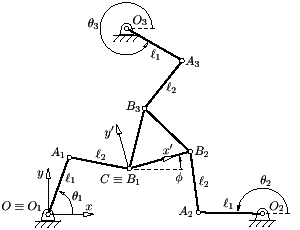
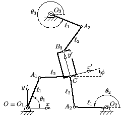
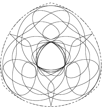
Examples of Singularity LociBelow is a number of examples of the singularity loci for all branch sets, shown together and separately, for different
general 3-RRR PPMs designs. To view the singularity loci for a particular branch set, simply move the
mouse cursor over the corresponding button. Note that the workspace boundary is represented in dashed line while the vertex
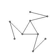
space centers are denoted by *. The design parameters that correspond to the singularity loci are listed below together
with a figure illustrating the PPM with the corresponding design and in the +++ branch set. Note also that the figures for the
different designs are not to the same scale.
Related Links
|
|
Home |
Bibliography |
Patents |
Terminology |
Reviews |
Software |
Who's Who |
News Site Map | Site Search | Contact Us | About Us |
| Copyright © 2000— by Ilian Bonev | Last Update: April 27, 2000 |


