The Parallel Mechanisms Information Center
(
http://www.parallemic.org)|
|
ParalleMIC The Parallel Mechanisms Information Center ( http://www.parallemic.org) |
|
This report explains the puzzling singularity of a translational parallel manipulator built at Seoul National University. We show that this is, in fact, a new type of singularity which can be referred to as a constraint singularity. This observation highlights the difficulties encountered in singularity analysis of parallel mechanisms with fewer than 6 degrees of freedom.
Parallel manipulators, with three translational degrees of freedom only, are of great interest for assembly and machining operations. The most popular translation parallel robot is the Delta robot designed by Reymond Clavel. Various other modified architectures have been proposed in the literature and some of them have been even commercialized. Examples of the latter are Krause & Mauser Group's Quickstep, INDEX Werke's VerticalLine V100, GROB Werke's TRIAGLIDE 5g, Renault Automation Comau's Urane SX, and others. All of them are based on the parallelogram principle.
A slightly different architecture of a 3-DOF 3-UPU translation parallel robot has been proposed in 1996 by Lung-Wen Tsai. In that design, the mobile platform is connected to the base through three identical legs. Each leg, comprises a prismatic actuator with two universal joints at the ends. The special arrangement of the axes of the universal joints, as seen on the figure below, provides the necessary constraint that keeps the orientation of the mobile platform always constant.
Tsai's translation parallel manipulator (courtesy of Prof. Lung-Wen Tsai)
Prior to the development of their ECLIPSE machining center, various other designs have been tested at Seoul National University. One of those desings, shown below, is a slight, yet critical, modification of Tsai's 3-UPU translational parallel robot. The difference is that the first axes (the ones fixed in the base) of the lower U-joints of the SNU manipulator do not form a triangle as in Tsai's robot but, instead, intersect at one common point. The same is true for the last axes (the ones fixed in the platform) of the upper U-joints. Note that in both designs, these axes are coplanar and lie in the base and platform planes, respectively.
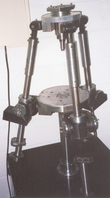
Seoul National University translational parallel robot
(photo taken by one of the authors, with Prof. Frank Park's permission)
Shortly after the final presentation at the 2nd Workshop on Computational Kinematics, May 22, 2001, there was a lab tour for the workshop participants. One of the parallel mechanisms that was built in attempts to find the perfect architecture for a machine tool was the manipulator shown on the photo above. The manipulator stood there motionless with its three legs set at equal lengths. All looked perfect until Prof. Frank Park pushed the mobile platform and the mechanism seemed to collapse under its weight. Naturally, the platform was no longer parallel to the base once deviated from its initial pose. At that time, Prof. Park commented that this apparent singularity could not be explained by the kinematic analysis of the mechanism. In fact, he mentioned that no one knew why the manipulator was singular.
Speculations were immediately made that the problem was due to an architecture singularity (see the section on that topic). But until the next morning, we didn't hear anyone come up with a plausible proof. Well, neither will we, since it seems to be quite difficult to actually prove that. However, we will later briefly outline the procedure that should be followed in order to obtain a straight answer to that question.
Now, let us put off for a while the question of whether this configuration is an architecture singularity or not. Firstly, let us see why it is a singularity at all. Prof. Tsai, and we guess Prof. Park too, derived the velocity equation of their mechanisms relating the actuator velocities and the linear velocity of the mobile platform:
Z v = w,
where v is the linear velocity of the platform and w is the vector of the three actuator velocities. The rows of the matrix Z are simply the unit vectors along the three legs. The velocity kinematics of many parallel manipulators can be described with an equation similar to the above, at least for most of their configurations. (For example, planar 3-RPR or the classic 6-UPS Stewart-Gough platform have such equations as long as their legs are not singular). What is usually understood when one speaks of a singularity of a parallel manipulator is a configuration where the matrix Z becomes singular. Such configurations are referred to by different authors as singularities of Type 2, parallel singularities, direct kinematic singularities, instabilities, or redundant output singularities. Compared to singularities of serial robots, where the end-effector loses a degree of freedom, "parallel singularities" seem to represent the opposite phenomenon. It is frequently, but incorrectly, said that, in such configurations, the platform "gains" a degree of freedom. Clearly a 6-DOF Stewart platform cannot gain a 7-th (?) DOF. A correct description is that one of the existing freedoms of the platform becomes uncontrollable and a non-zero output motion exists even when the actuator velocities are zero. The mathematical explanation is that this motion is in the kernel of Z.
For a positioning (or translational) mechanism, such as the SNU one, a parallel singularity would mean that there is an uncontrollable translation, and that the platform can translate even with locked actuators. However, in the shown configuration, where all legs are of equal length, the Z matrix of the SNU mechanism is not singular. In fact, if the legs are at right angles Z will be the unit matrix and the configuration will be isotropic! The geometric conditions for singularity of that matrix are for the platform and base planes to coincide or for the platform and base to be identical. The latter is, in fact, an architecture singularity. So Z is not singular. Is there no singularity?
Close inspection shows that when the actuators are locked, the platform cannot translate with respect to the base. So, indeed, there is no classic parallel singularity. But the platform is unstable and can move. How can this be? The answer is that, in this configuration, the mechanism ceases to be translational and the platform can rotate. In other words, here the mechanism has indeed gained a new additional rotational freedom.
What are the necessary conditions for our 3-UPU mechanisms to work for translations only? Prof. Tsai stated in his latest article, that those are: (1) the first revolute joint axis to be parallel to the last revolute joint axis; and (2) the two intermediate revolute joint axes to be parallel to one another. Well, those are satisfied in the SNU mechanism, even in the configuration in question.…
Why does the mobile platform have only translational degrees of freedom? The constraint that each leg imposes on the mobile platform, when the latter has the same orientation as the base, is that the platform may not rotate about an axis normal to the two parallel U-joint planes. If the three pairs of U-joint planes for all three legs do not intersect at a common line then the mobile platform cannot rotate about three linearly independent axes and, hence, cannot rotate at all. In the contrary case, the platform cannot rotate about only two axes (if the planes intersect at a common line) or even about only one (if the planes are all parallel). To the best of our knowledge, these two cases have never been considered before. We will name this special type of singularity as the constraint singularity.
The above paragraph can be rewritten in an entirely rigorous way using the language of screw theory. The reciprocal system of a leg is the system of wrenches that can be resisted by the leg with no effort in the actuators. The vector-space sum of reciprocal screw systems of the legs is the system of the constraining wrenches of the mechanism. The true condition for a parallel mechanism to be translational is that the system of the constraining wrenches contains as a subspace the three-system of all pure moments. The system of the possible platform twists is the reciprocal to the system of constraining wrenches. If all moments are among the constraining wrenches then only translations will comprise the possible platform twists.
For the SNU manipulator, as long as the two U-joints are parallel, the reciprocal system of each leg is a pure moment perpendicular to the U-joint plane. The system of the constraining wrenches is spanned by the three reciprocal moments of the three legs. When these are moments about three linearly independent directions, all pure moments will be constraining wrenches.
However, in the studied configuration, the planes of all U-joints are parallel. The reciprocal moments of all three legs are identical. Hence, the system of the constraining wrenches of the mechanism consists of only one screw — the vertical moment. Hence, the twist system of the platform is a five-system and, since the mechanism has five instantaneous DOFs, it is no longer translational.
What exactly are the new motions that the mechanism can perform when the actuators are locked? To see this we need to find the constraining wrenches of the same mechanism but as if there were no prismatic joints. The reciprocal system of each leg is now a two-system spanned by the vertical moment and a pure force along the leg. The constraining wrenches then form the four-system spanned by all forces passing through the point at which all three legs intersect, as well as the pure moment about the vertical direction. Hence, the motion system of the platform twists is the two-system of all rotations with horizontal axes through the legs' intersection point. So, there are two new uncontrollable freedoms of the platform.
It is possible to show that generally Prof. Tsai's mechanism does never encounter a constraint singularity (unless the base and platform are identical). This is not true for the SNU mechanism, however. In fact in configurations, where all legs are of equal length, all pairs of U-joint planes are parallel. Hence, the mechanism gains two uncontrollable degrees of freedom. The latter are the (instantaneous?) rotations about any horizontal axis passing through the intersection point of the legs. This is the only type of configurations where two uncontrollable freedoms are gained. It is not obvious, however, whether there are not other configurations where one uncontrollable freedom is gained.
Designers often tend to build parallel manipulators that have highly symmetric and simplified geometries. One major reason for doing so is that such designs are usually associated with a simple solution to the direct kinematic problem. These designs are often analyzed in detail, leading to highly satisfactory results (isotropy, large workspace, etc.), and then even built … only to see that they do not work. Such a notorious example is the 6-DOF 6-UPS Stewart-Gough platform designed and patented by Prof. Michael Griffis and Prof. Joseph Duffy at the University of Florida. Their parallel mechanism was later found to be architecture singular by Prof. Manfred Husty.
Architecture singularities or self motions are associated with mechanisms whose end effector is able to undergo an uncontrollable motion even when all of its actuators are locked. The simplest example of such a self motion is the one that occurs in a Stewart-Gough platform when its mobile platform is identical to its base and has the same orientation. Such architecture singularities are generally not easy to detect and are not obvious from the velocity equation of the mechanism. However, they are not the main subject of our review.
To give an answer to that question, the problem needs to be formulated geometrically. Referring to the photo of the SNU manipulator, let us denote by Ai and Bi (i = 1, 2, 3) the centers of the base and platform U-joints, respectively. Let the geometrical centers of the equilateral triangles A1A2A3 and B1B2B3 be denoted by O and C, respectively. Additionally, let O be the center of the base frame and points Ai be in the xy plane. Let the length of all legs be equal to l, and let the length of the sides of the platform triangle be denoted by b. Let us finally denote the coordinates of points Bi by xi, yi, and zi (i = 1, 2, 3).
The particular arrangement of the U-joints in a leg ensures that the axes of the R joints attached to the base and the platform (a U-joint is composed of two R joints whose axes are perpendicular) stay always in one plane. Since point O lies on all three base axes and point C lies on all three platform axes, it follows that all three leg planes intersect at one common line, passing through the base and platform centers (see the figure below).
Schematic of Seoul National University translational parallel robot
Note that wherever the mobile platform is, the full set of constraints imposed by the legs are that points
Bi should lie on three spheres of radius l and centers at points
Ai (i = 1, 2, 3). In addition, the distance between any two points on
the platform should be b. Finally, points Ai, Bi,
C, and O should be coplanar. In other words, we need to solve the following system of 9 quadratic
equations in 9 unknowns (the coordinates of points Bi):
|
(x1 - xA1)² + (y1 - yA1)² + z1² = l² (x2 - xA2)² + (y2 - yA2)² + z2² = l² (x3 - xA3)² + (y3 - yA3)² + z3² = l² (x1 - x2)² + (y1 - y2)² + (z1 - z2)² = b² (x3 - x2)² + (y3 - y2)² + (z3 - z2)² = b² (x1 - x3)² + (y1 - y3)² + (z1 - z3)² = b² (z1y2 + z1y3 - y1z2 - y1z3)xA1 + (x1z2 + x1z3 - z1x2 - z1x3)yA1 = 0 (z1y2 + y2z3 - y1z2 - z2y3)xA2 + (x1z2 + z2x3 - z1x2 - x2z3)yA2 = 0 (y1z3 + y2z3 - z1y3 - z2y3)xA3 + (z1x3 + z2x3 - x1z3 - x2z3)yA3 = 0 |
where (xAi , yAi , 0) are the coordinates of points Ai (i = 1, 2, 3).
If the real solution to that system when point C lies on the z axis is isolated, then there is no architecture singularity and the uncontrollable motion associated with the constraint singularity is infinitesimal. On the other hand, if that solution is not isolated, there is an architecture singularity and the uncontrollable motion associated with the constraint singularity is finite.
We believe that there is no architecture singularity. Rather, the collapse is simply initiated by the constraint singularity and is due to manufacturing tolerances and flexibility in the U-joints. If, however, there were an architecture singularity, then the SNU mechanism would be a truly novel (2-DOF?) orientation mechanism. The main contribution of this report is, however, the newly defined constraint singularity. It should be obvious from this report that there is more to the singularity analysis of parallel mechanisms than the identification of the classical "parallel singularities".
| |
Tsai, L.-W., "Kinematics of a Three-DOF Platform With Extensible Limbs," Recent Advances in Robot Kinematics, J. Lenarcic and V. Parenti-Castelli (eds.), Kluwer Academic Publishers, pp. 401-410, 1996. |
| |
Tsai, L.-W., "Kinematics and Optimization of a Spatial 3-UPU Parallel Manipulator," ASME Journal of Mechanical Design,
Vol. 122, pp. 439-446, December, 2000.
|
| |
Ma, O., and Angeles, J., "Architecture Singularities of Platform Manipulators," Proc. IEEE International Conference on Robotics and Automation, Sacramento, CA, USA, April 11-14, pp. 1542-1547, 1992. |
| |
Karger, A., and Husty, M., "On Self-Motions of a Class of Parallel Manipulators," J. Lenarcic and V. Parenti-Castelli (eds.), Kluwer Academic Publishers, pp. 339-348, 1996. |
| Copyright © 2000– by Ilian Bonev | Last Update: June 12, 2001 |