The Parallel Mechanisms Information Center
(
http://www.parallemic.org)|
|
ParalleMIC The Parallel Mechanisms Information Center ( http://www.parallemic.org) |
|
The serial arrangement of a planar kinematic bond and a spherical bond has remarkable properties which play a key role in several already described parallel mechanisms. Furthermore, new mechanisms are discovered through the systematic study of the planar-spherical bond. Firstly, it is worth recalling that the displacement set {D} is a Lie group and that planar gliding motions {G(u)} perpendicular to the unit vector u as well as spherical motions {S(N)} around the point N are Lie subgroups of {D}. Then {G(u)} and {S(N)} have several equivalent mechanical generators, each of which are made of sequences of lower kinematic pairs. The intersection set {G(u)} ^ {S(N)} is equal to the one-dimensional Lie subgroup {R(N,u)} of rotations about the axis determined by (N,u). This implies a rotational passive mobility of the rigid body, which intermediates between the planar bond and the spherical bond. Then, the degree of freedom (DOF) of a planar-spherical bond is 5 instead of 6, obtained by adding the 3 DOF of a planar bond and the 3 DOF of a spherical bond. Numerous sequences of lower kinematic pairs are proven to be equivalent and generate the 5 DOF planar-spherical bond without passive mobility. The setting in parallel of planar-spherical bond generators produces a new bond which depends on the relative positions of planes and sphere centers. This way, families of novel kinematic architectures for parallel mechanisms are found.
1.1. Geometrical Notations
In classical mechanics, the set of geometrical points is a 3-dimensional Euclidean affine space E. In this article, the
elements of E are denoted by capital characters, for example M, N, P… The set of vectors is the 3-dimensional
Euclidean vector space E and vectors are represented by bold letters, U,V,V'… Small bold
letters indicate unit vectors, for example i, j, k… Vectors obtained from a pair of points, for example N
and M, are denoted by a pair of bold letters, for example (NM). The cross × means vector product and u×
is the linear skew symmetric operator of the vector product by u.
A displacement is a point transformation, which maintains both vector lengths and orientation of any vector base. Thus, displacements represent rigid body motions. An operator D acting on a generic point M, which is transformed into M', will be used as a displacement notation. Otherwise, one can write:
M —> M' = D M.
According to the Mozzi-Chasles theorem, except for the pure translation case, any displacement is a screw motion, and therefore it can be explicitly written as
M —> M' = D M = N + k æ u + exp(æ u×) (NM).
If O is any given origin, the following expression is equivalent to the previous one:
(OM) —> (OM') = D (OM) = (ON) + k æu +
exp(æ u×) (NM)
Here, (N, u) is a frame of reference of the screw axis, which is a 1-dimensional affine subspace of E; N can be changed into another point N' if and only if we have
u×(NN') = 0.
The variable æ is the angle and 2πk is the pitch of the screw motion. We have
exp(æ u×) = 1 + æ / 1! u× + æ2 / 2! (u×)2 + … + æn / n! (u×)n + ….
Using (u×)3 = – u× , we obtain the modern expression of the Olinde-Rodrigues formula:
exp(æ u×) = 1 + sin æ u× + (1 – cos æ) (u×)2,
exp(æ u×) (NM) = (NM) + sin æ u×(NM) + (1 – cos æ) u× [u×(NM)].
A purely translational displacement T requires a special formulation:
M —> M' = T M = M + T,
where T is the translation vector.
1.2. Group Properties
One can readily verify that the displacement set has the algebraic properties of a group. A group is a set endowed with an associative
closed product, the identity belongs to the group and any element has an inverse. It is almost evident that the product of two
successive displacements is another displacement. The identical transform E is a displacement (æ = 0 in the previous
formulas) and the inverse D-1 of a displacement D is also a displacement (change of æ by –æ).
The displacement set is a 6-dimensional manifold. The components in a frame of reference of the rotation vector R = æ u and those of the translation vector T = (ON) + k æ u can be used as the six scalar parameters of any displacement. In another approach any non-translational displacement can be characterized by the axis datum (4 parameters) together with the angle and the pitch. One can establish that the displacement group is more precisely a Lie group by examining the specific continuity properties.
The Lie subgroups of the displacement group are the cornerstone of the structural synthesis of mechanisms. The following list shows the motion types, which are endowed with the algebraic structure of a Lie group. Employing the language of group theory, these motion types are actually conjugacy classes. Most of these subgroups have a usual name. However the X motion type will be called Schoenflies motions because A. Schoenflies studied at some length this motion type at the end of the ninetieth century. The Y motion type can be named pseudo-planar motion because of its great analogy with planar gliding motions G.
The comprehensive list of displacement Lie subgroups is recalled below (Hervé):
| {E} | identity |
| {T(u)} | translations parallel to the vector u |
| {R(N,u)} | rotations around the axis determined by N and u |
| {H(N,u,p)} | helical or screw motions with the axis (N,u) and the pitch p = 2πk |
| {T(Pl)} | translations parallel to the plane Pl |
| {C(N,u)} | cylindrical motions or combined rotations and translations along an axis (N,u) |
| {T} | spatial translations |
| {G(Pl)} or {G(v)} | planar gliding motions parallel to the plane Pl or perpendicular to v |
| {Y(w,p)} | planar translations perpendicular to w combined with screw motions of pitch p along any axis parallel to w or pseudo-planar motions; {Y(w,0)} = {G(w)} |
| {S(N)} | spherical rotations about point N |
| {X(w)} | translating hinge motions allowing spatial translations and rotations around any axis parallel to w or Schoenflies motions |
| {D} | general rigid body motions or displacements |
1.3. Kinematic Bonds
A kinematic bond (mechanical bond or liaison) {L(1,2)} between two rigid bodies 1 and 2 is the set of allowed relative
displacements between two rigid bodies. Curly brackets indicate the sets. Generally a kinematic bond is a manifold in the displacement
set. Discontinuous kinematic bonds are out of the scope of this article. The dimension of this manifold is the degree of freedom of
the kinematic bond. When the kinematic bond is a Lie subgroup of displacements, any mechanical system, which produces the bond is a
mechanical generator of the displacement subgroup.
The serial arrangement of two bonds {L(1,2)} and {L(2,3)} generates a new bond {L(1,3)} between the bodies 1 and 3. This new bond is said to be the composed bond. Using intrinsic (frame free) notations of displacements for example those of Section 1.1, the composed bond is obtained simply by using the product of displacements:
{L(1,3)} = {L(1,2)} . {L(2,3)} = {L(1,2) . L(2,3)}.
The setting in parallel of two bonds {L(1,2)} and {L'(1,2)} creates a new bond between the bodies 1 and 2, which is the intersection set {L(1,2)}^ {L'(1,2)}.
When one describes a kinematic chain, the kinematic bonds of the kinematic pairs are given by the hypothesis. Any bond between any couple of rigid bodies can be determined just employing step by step the composition and the intersection of bonds.
1.4. Lie Subgroup Generators
The displacement Lie subgroups are generated by equivalent kinematic chains called subgroup generators. For sake of simplicity, only
opened single-loop chains made of lower kinematic pairs will be considered in this disclosure.
As an example, the subgroup of cylindrical motions {C(A,u)} will be emphasized. This subgroup can be generated by mere a cylindrical pair C but can be produced also by several sequences of two kinematic pairs chosen among R (revolute), H (helical), P (prismatic pair). For example a sequence of two coaxial helical pairs H-H will be proven equivalent to a C pair as being a generator of the subgroup {C(A,u)}. The first H pair produces the subgroup {H(A, u, p)}, the second H pair the subgroup {H(A, u, q)}. A is a point on the screw axis, u is a unit vector parallel to this axis and p is the pitch of the first screw. (A, u, q) characterizes in the same manner the second screw in its given position (or initial position). The bond between the first body and the end body is given by the following product
{H(A, u, p) . H(A, u, q)} = {H(A, u, p)} . {H(A, u, q)}.
The subgroups {H(A, u, p)} and {H(A, u, q)} are included (≤) in the subgroup {C(A, u)} of cylindrical motions, which combines rotations {R (A, u)} about the axis (A, u) with translations {T(u)} parallel to u. In other words,
{H(A, u, p)} ≤ {C(A, u)} and
{H(A, u, q)} ≤ {C(A, u)} imply,
{H(A, u, p)} . {H(A, u, q)} ≤ {C(A, u)},
because of the product closure in the subgroup {C(A, u)}.
{H(A, u, p)} . {H(A, u, q)} is a 2-dimensional manifold included in the 2-dimensional subgroup {C(A, u)}. A difference between {H(A, u, p)} .{H(A, u, q)} and {C(A, u)} can only originate from different intervals of variation for the parameters. Dealing with motion types, such a difference is ignored and the sequence of two coaxial screws is called a mechanical generator of the subgroup {C(A, u)}:
{H(A, u, p)} . {H(A, u, q)} = {C(A, u)},
the equality being proven only in a finite neighborhood of the identity.
Figure 1 shows the schematic drawings of the generators of a cylindrical subgroup. The sketch 1(e) illustrates the previous reasoning. All these generators are equivalent to a C pair with respect to the bond generation.
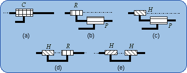
Figure 1: Equivalencies of C.
1.5. Equivalencies of the Spherical Joint
A spherical pair S (ball-in-socket joint) of center N is directly associated to the subgroup of spherical rotations
(orientational motions) around N namely {S(N)}. Any element of such a subgroup is represented in an orthogonal frame of
reference having the origin N, by a 3x3 special orthogonal matrix (special stands for positive determinant of the matrix). The set of
these matrices is usually denoted SO(3). However it is worth noticing that the confusion of matrices with point transformations hides
the reasoning between intrinsic geometrical entities.
The Lie subgroups of a given {S(N)} are the subgroups of rotations about given axes, which contain the given point N. Then such axes can be designated by (N, u) or (N, v), etc., and the corresponding rotations subgroups are {R(N,u)}, {R(N,v)},…
Since {R(N,u)} < {S(N)} and {R(N,v)} < {S(N)}, we have
{R(N,u)} . {R(N,v)} ≤ {S(N)}
because of the product closure in the subgroup {S(N)}. Also, {R(N,w)} < {S(N)} implies that
{R(N,u)} . {R(N,v)} . {R(N,w)} ≤ {S(N)}.
If {R(N,u)}.{R(N,v)}.{R(N,w)} is a 3-dimensional manifold of the 3-dimensional subgroup {S(N)}, the difference between {R(N,u)}.{R(N,v)}.{R(N,w)} and {S(N)} can only come from the amplitude of the parameter variations. Then two finite neighborhoods of the identity in {R(N,u)}.{R(N,v)}.{R(N,w)} and in {S(N)} are equal. Dealing only with motion types, the resulting formula can be written
{R(N,u)} . {R(N,v)} . {R(N,w)} = {S(N)}.
That previous formula fails if and only if u, v, w are linearly dependent. The linear dependency provokes infinitesimal or finite passive mobility as it is well established by screw theory in kinematics. Screw theory is actually the theory of infinitesimal displacements. Then three revolute R pairs whose axes intersect at N are equivalent to a spherical S pair centered at N, provided the three R axes make up a vector base.
Two possible systems, 2(b) and 2(b'), of three revolute R pairs with orthogonal axes are exhibited in Fig. 2 as being
equivalent to a spherical S pair. One has to remember that these sketches are special cases of more general possible devices as
above described.
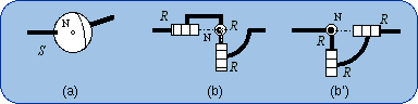
Figure 2: Equivalencies of S.
1.6. Equivalencies of the Planar Joint
The planar pair Pl generates the subgroup {G(Pl)} where Pl designates either the kinematic pair or the
direction of the given plane. Let w be a unit vector, which is perpendicular to Pl. The same subgroup can also be denoted
{G(w)} without shortcoming.
Lie subgroups of {G(w)} are {R(A, w)} where the points A can freely be chosen and {T(u)} where u has to be parallel to Pl (or perpendicular to w). Using the previous method one can readily prove the equivalencies shown in Fig. 3. For example, the equivalency 3(b) will be demonstrated by the formula
{G(w)} = {R(A, w)}.{R(B, w)}.{R(C, w)}.
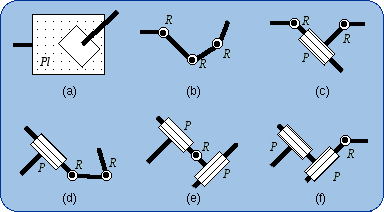
Figure 3: Equivalencies of Pl.
These equivalencies are valid if and only if there is no infinitesimal or finite passive mobility that can be found employing the screw theory, which is out of the scope of this short article. An infinitesimal passive mobility may happen if three R pair axes are in a plane or if the direction of a P pair is perpendicular to the plane of two R pair axes. A finite passive mobility will occur when two R pairs are coaxial or two P pairs are parallel. These singular configurations are supposed to be avoided in the following disclosure.
2.1. Definition
The bond generated by a serial arrangement Pl-S of a planar pair Pl and a spherical pair S will be called
planar-spherical bond (Fig. 4a). Let N be the center of the S pair and w a unit vector perpendicular to the plane
Pl. The bond will be represented by the expression {G(w)} . {S(N)}.
The sequence of the two lower pairs Pl and R can be replaced by a single higher pair that takes birth from the punctual contact of a sphere on a plane (Fig. 4b). The intermediate body (shown in dark blue in Fig. 4a) plays no role in the mechanical connection of the first body and the end body.
The size of the sphere can be changed without modifying the bond. What is essential is the planar motion of the sphere center N. In a limit case, the sphere diameter is equal to zero and then the sphere is reduced to its center, which is also the contact point on the plane (Fig. 4c).
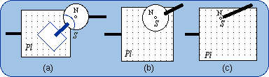
Figure 4: The serial bond (planar pair – spherical pair) or planar-spherical bond Pl-S.
2.2. Degree of Freedom
In the generic realization of a planar-spherical bond (Fig. 4a), the intermediate body (in dark blue) can rotate around the
(N, w) axis without modifying the position of the end body with respect to the first body. This passive mobility diminishes the
degree of freedom of the bond, which is (3 + 3) - 1 = 5. This result can be explained employing group theory. In any group, the
intersection set of two subgroups is always a subgroup. In the displacement group {D}, the subgroup intersection of
{G(w)} and {S(N)} is the subgroup {R(N, w)}:
{G(w)} ^ {S(N)} = {R(N, w)}
The subgroup {G(w)} can be decomposed into a product (see Section 1.6):
{G(w)} = {R(A, w)} . {R(B, w)} . {R(N, w)}
The subgroup {S(N)} can be decomposed into a product (see Section 1.5) too:
{S(N)} = {R(N, w)} . {R(N, v)} . {R(N, u)}
Then the planar-spherical bond can therefore be written as
{G(w)} . {S(N)} = {R(A, w)} . {R(B, w)} . {R(N, w)}
. {R(N, w)} . {R(N, v)} . {R(N, u)}
= {R(A, w)} . {R(B, w)} . {R(N, w)}2 . {R(N, v)}
. {R(N, u)}
We have {R(N, w)}2 = {R(N, w)} because of the product closure in the subgroup
{R(N, w)}. Therefore
{G(w)} . {S(N)} = {R(A, w)} . {R(B, w)} . {R(N, w)} . {R(N, v)} . {R(N, u)}
The five DOF of the planar-spherical bond are explained by means of a product of five one-dimensional subgroups and therefore can be realized by a sequence of five 1-DOF kinematic pairs (Fig. 5).
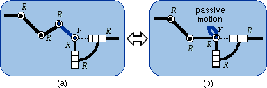
Figure 5: Elimination of the passive mobility.
Conversely, in the 5-R chain, either a spherical pair S or a planar pair Pl can be substituted to a sequence of three R pairs whose axes are either intersecting or parallel. Otherwise, two representations are obtained for the Pl-S bond:
{G(w)} . {S(N)} = {G(w)} . {R(N, v)} . {R(N, u)}
{G(w)} . {S(N)} = {R(A, w)} . {R(B, w)} . {S(N)}
This leads to two subfamilies of Pl-S equivalencies, namely the subfamily Pl-(RR) (Fig. 6a) and the subfamily RR-S (Fig. 6b). By convention, the underlined is a planar subsystem and what is between brackets is a spherical subsystem.
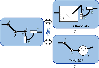
Figure 6: Obtaining two families of equivalencies.
2.3. The Pl-(RR) Family
The schematic drawings of Fig. 7 are projections in the plane Pl.
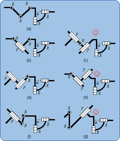
Figure 7: Members of the family Pl-(RR).
In Fig. 7(a), the Pl pair is made equivalent to a sequence of three R pairs with parallel axes of direction w; the remaining two R pairs have intersecting axes of common point N. These last axes should not be parallel to w but are not necessarily perpendicular to w as they are shown in Fig. 7.
Using all the equivalencies of Pl (Fig. 3) yields the generators of the Pl-S
bond, which are shown in Fig. 7. In the sketches in
Figs. 7(c,e,g), there is a sequence P-R that is marked with
![]() and the parallelism between
the P direction and the R axis is allowed. Then the sequence P-R can be merged into a C pair. The
equivalencies of C can be used thus leading to the PR(C-R), RP(C-R) and
RR(C-R) subfamilies of the Pl-S bond generators. In these subfamilies, the C pair axis has to
be parallel to the plane Pl whereas in the initial P-R sequence the R pair axis can be non parallel to Pl.
and the parallelism between
the P direction and the R axis is allowed. Then the sequence P-R can be merged into a C pair. The
equivalencies of C can be used thus leading to the PR(C-R), RP(C-R) and
RR(C-R) subfamilies of the Pl-S bond generators. In these subfamilies, the C pair axis has to
be parallel to the plane Pl whereas in the initial P-R sequence the R pair axis can be non parallel to Pl.
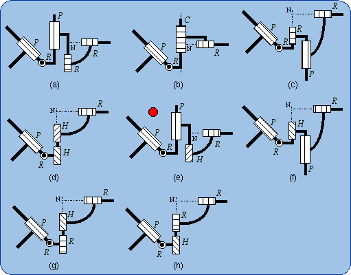
Figure 8: Members of the subfamily PR(C-R).
The subfamily PR(C-R) is shown in Fig. 8. The subfamilies RP(C-R) and RR(C-R) are presented in Fig. 9 and Fig. 10.
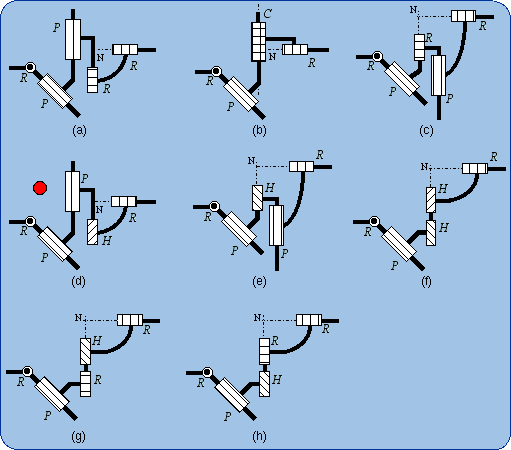
Figure 9: Members of the subfamily RP(C-R).
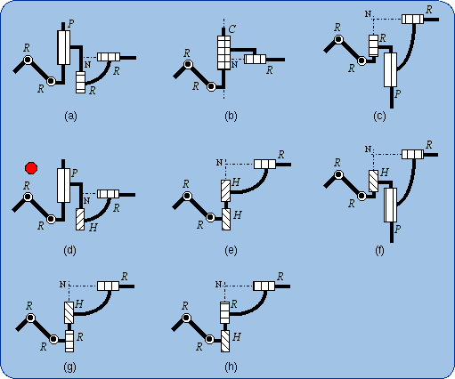
Figure 10: Members of the subfamily RR(C-R).
In Fig. 8(e), one can remark that the sequence PRP is equivalent to Pl.
Analogous equivalencies that are marked ![]() can be found in Figs. 9(d) and 10(d). The new subfamily Pl-(HR) is thus
discovered (Fig. 11). The kinematic chains of Figs. 11(c,e,g) are more general than the previously found chains in
Figs. 8(e), 9(d) and 10(d). It is worth noticing that in chains of the Pl-(HR) subfamily,
the H axis has to be parallel to Pl, the R axis being non perpendicular to Pl.
can be found in Figs. 9(d) and 10(d). The new subfamily Pl-(HR) is thus
discovered (Fig. 11). The kinematic chains of Figs. 11(c,e,g) are more general than the previously found chains in
Figs. 8(e), 9(d) and 10(d). It is worth noticing that in chains of the Pl-(HR) subfamily,
the H axis has to be parallel to Pl, the R axis being non perpendicular to Pl.
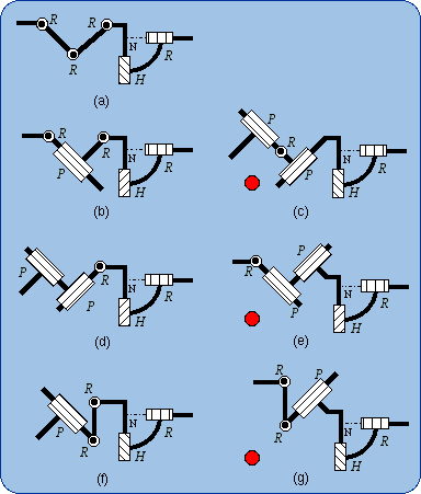
Figure 11: Members of the subfamily Pl-(HR).
2.4. The RR-S Family
The so-called RR-S family is actually obtained by removing one R in a planar motion generator and keeping a full
spherical generator. Figure 12 shows all possible combinations. The spherical pair S can be replaced by any sequence
(RRR) with converging axes and linearly independent directional vectors. The corresponding drawings are not explicitly exhibited.
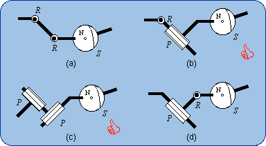
Figure 12: Members of the subfamily RR-S.
In Figs. 12(b,c), a prismatic pair P that is marked with
![]() can be
merged with a parallel R pair of a virtual (RRR) sequence, which is equivalent to the S pair, PR then
becoming equivalent to C. Using the equivalencies of C, the subfamilies R(C-RR) and
P(C-RR) are discovered (see Figs. 13 and 14).
can be
merged with a parallel R pair of a virtual (RRR) sequence, which is equivalent to the S pair, PR then
becoming equivalent to C. Using the equivalencies of C, the subfamilies R(C-RR) and
P(C-RR) are discovered (see Figs. 13 and 14).
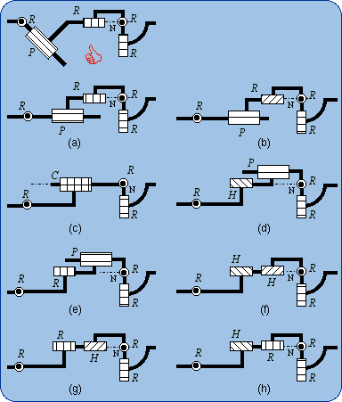
Figure 13: Members of the subfamily R(C-RR).
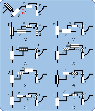
Figure 14: Members of the subfamily P(C-RR).
3.1. Introduction
Two planar-spherical bonds are given by two planes Pl, Pl' (or by their perpendicular unit vectors w, w')
and by two points N, N'. The first planar-spherical bond is {G(w)} . {S(N)} and the second
{G(w')} . {S(N')}. Setting in parallel the two Pl-S bonds produces the intersection bond
{G(w)} . {S(N)} ^ {G(w')} . {S(N')}.
This bond includes the sets {G(w)} ^ {G(w')} and {S(N)} ^ {S(N')}, which are obtained respectively by locking the spherical motion parameters or those of the planar motions. As a matter of fact, {S(N)} and {S(N')} can be {E}, and also {G(w)} and {G(w')} can be {E}, the subgroup made of only the identical transform E.
Hence this bond depends on the relative situation of the planes and sphere centers. Depending on the relative situation of the planes we may have
{G(w)} ^ {G(w')} = {T(u)},
u = (w × w') / |w × w'| if w ≠ w' or
{G(w)} ^ {G(w')} = {G(w)} if w = w'
(or Pl //Pl')
and depending of the sphere centers we may have
{S(N)} ^ {S(N')} = {R(N, i)}, i= (NN') / |NN'| if
N ≠ N' or
{S(N)} ^ {S(N')} = {S(N)} if N = N'
These different circumstances lead to four types of parallel arrangements of planar-spherical bonds, namely the general case (w ≠ w', N ≠ N'), the common-plane case (w = w', N ≠ N'), the common-center case (w ≠ w', N = N') and the identical-bond case (w = w', N = N').
3.2. The General Case
The two parallel planar-spherical bonds are then fully distinct. A possible real achievement of this case can be easily obtained by the
punctual contact of two rigidly connected spheres on two welded intersecting planes (Fig. 15a).
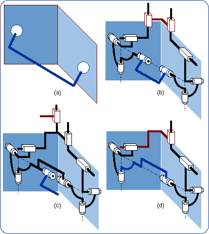
Figure 15: Parallel fully distinct planar-spherical bonds.
Using one among the numerous previous equivalencies of the planar-spherical bond, namely the generator PP(RRR) (Fig. 12c) for each of the two planar-spherical bonds we obtain Fig. 15(b). The first P pairs are chosen parallel to the two planes intersection and the last R pair has the same axis that is the line of the sphere centers. Then, the single-loop closed chain includes two bodies, which can move passively with respect to the chain mobility. The passive mobility of the closed chain can be eliminated thus giving the closed chain of Fig. 15(d). The intersection of the two planar-spherical bonds can therefore be generated by the hybrid sequence P—[closed chain]—R of Fig. 15(c). The closed loop of Fig. 15(d) has two DOF and the double planar-spherical bond is 4-dimensional as predicted by the Gruebler-Kützbach formula. A representation of this bond may be (u parallel to Pl and Pl'):
3.3. The Common-Plane Case
Figure 16(a) shows a dark blue body with two spheres that have two contacts with two pale blue parallel planes. It is almost evident
that rotations are allowed around the line of the sphere centers and that this axis can glide along a plane. Hence the bond is
equivalent to the bond produced by a sequence of a planar pair and a revolute pair (Fig. 16b). Figure 16(c) shows an example
of parallel arrangement of two planar-spherical bond generators RR-S (Fig. 12a) when the planes are parallel and the sphere
centers are distinct.
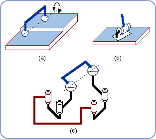
Figure 16: Parallel planar-spherical bonds with parallel planes.
The resulting kinematic bond is 4-dimensional and its representation may be
{G(Pl)} . {R(N, i)}.
3.4. The Common-Center Case Figure 17(a) shows a dark blue body with two concentrical spheres that can be merged into only one sphere that has two contacts with two intersecting planes. It is almost evident that translation is allowed along the line of the plane intersection. Hence the bond is equivalent to the bond produced by a sequence of a prismatic pair and a spherical pair (Fig. 17b). Figure 17(c) shows an example of parallel arrangement of two planar-spherical bond generators RRR-(RR) (Fig. 7a) when the planes intersect and the sphere centers coincide. This 4-dimensional bond can be represented by {T(u)} . {S(N)}.
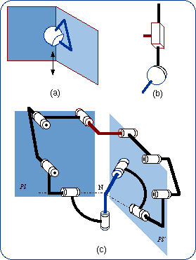
Figure 17: Parallel planar-spherical bonds with a common center.
Zlatanov and Gosselin (2002) have described many of the kinematic structures that are in this case.
3.5. The Identical-Bond Case In this case the parallel planes and the concentrical spheres (Fig. 18a) can coincide thus being equivalent to a single 5-DOF higher kinematic pair (Fig. 18b). The parallel arrangement of two limbs produces the planar-spherical bond, which is generated by only one limb. Figure 18(c) shows a parallel setting of two limbs of the type given in Fig. 7(g). Several mechanisms belonging to this 5-DOF type are described by Huang and Li (2002).
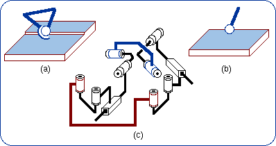
Figure 18: Parallel planar-spherical bonds with a common center and parallel planes.
4.1. Introduction
The number of relative situations of three planes and three spheres is greater than in the case of only two planar spherical bonds.
Only structurally symmetrical parallel mechanisms are considered in this article.
Three planes may be parallel, parallel to a line or non parallel that is intersecting. Three sphere centers may be coincident, on a line or non-colinear. Hence we have nine possible relative configurations, namely: 3-parallel-planes/3-coincident-centres, 3-parallel-planes/3-aligned-centers, 3-parallel-planes/3-noncolinear-centres, 3-line-parallel-planes/3-coincident-centres, 3-line-parallel-planes/3-colinear-centres, 3-line-parallel-planes/3-noncolinear-centres, 3-intersecting-planes/3-coincident-centres, 3-intersecting-planes/3-colinear-centres, 3-intersecting-planes/3-noncolinear-centres.
4.2. Parallel Planes
4.2.1. Coincident sphere centers: this configuration is merely the addition of a limb in the case studied in Section 3.5.
Some architectures of this parallel mechanism type have been described by Huang and Li (2002) as
mentioned in Section 3.5, and the number of limbs can be five in order to actuate the five degrees of freedom of the moving
platform in a fully parallel manner.
4.2.2. Colinear sphere centers: this configuration actually corresponds to the addition of a compatible limb in the case studied in Section 3.3. The fully parallel actuation requires four limbs.
4.2.3. Non-colinear sphere centers: the moving platform will undergo planar displacements (Fig. 19a). Actually this case gives non-overconstrained planar parallel mechanisms. The generated bond is equivalent to a planar pair (Fig. 19b). Figure 19(c) shows an example, which implements three limbs R(CRR) of Fig. 13(a).
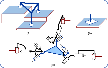
Figure 19: Parallel planar-spherical bonds producing planar displacements.
4.3. Line-Parallel Planes
4.3.1. Coincident sphere centers. In this case, the three spheres are equivalent to only one sphere and the sphere center can
move along a straight line parallel to three planes as explained in Section 3.4 (Fig. 17). Two limbs are enough to produce
the kinematic constraint and therefore the third limb is an overconstraint. Zlatanov and Gosselin (2002) have described most of the
limb arrangements in this case. However, the authors have forgotten the possible implementation of screw pairs.
4.3.2. Colinear sphere centers The parallel mechanisms shown in Fig. 20 have some analogy with those of Section 3.2. The three degrees of freedom of the moving platform can be produced by a sequence P-[1-DOF generated by a closed loop chain]-R.
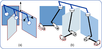
Figure 20: Parallel planar-spherical bonds with three planes parallel to a line and three colinear centers.
4.3.3. Noncolinear sphere centers. In the particular case when the three planes are intersecting at one line and make equal 120° angles, and the three sphere centers are equidistant, the type of the allowable platform motion was studied by Bonev et al. (2002). In its special form of Fig. 21(b) (see Fig. 12a), this type of 3-DOF parallel mechanism has been presented by Lee and Shah (1987). If the moving platform can always undergo linear translation, other allowed motions generally are helical and sometimes can be rotational. The MIPS of J.-P. Merlet benefits by the version shown in Fig. 21(d) (legs of Fig. 12d). P. Huynh made a full development of the mechanism of Fig. 21(c) (legs of Fig. 12b), the prismatic pairs being actuated.
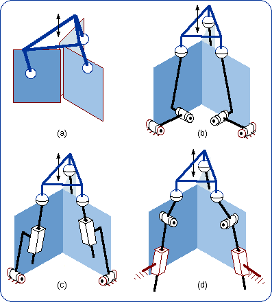
Figure 21: Parallel planar-spherical bonds with three planes parallel to a line.
4.4. Intersecting Planes
4.4.1. Coincident sphere centers. In this case, the common sphere center cannot move and any parallel mechanism is equivalent to
a spherical joint (Figs. 22a and 22b). The corresponding parallel mechanisms are orientational 3-DOF wrists. These parallel wrists
belong to the comprehensive list of non-overconstrained spherical tripods that were obtained by
Karouia and Hervé (2000; 2002). An example of a novel wrist is shown in Fig. 22(c). In
this example, each limb produces a planar-spherical bond by the mechanical system of Fig. 11(a).
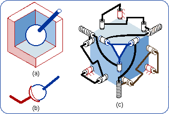
Figure 22: Parallel planar-spherical bonds making up a wrist.
4.4.2. Colinear sphere centers. The generated 3-dimensional bond is the product of a 2-dimensional bond by the subgroup of rotations around the center line.
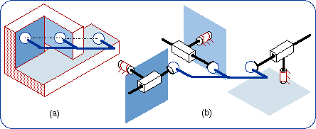
Figure 23: Parallel planar-spherical bonds with colinear centers.
4.4.3. Non-colinear sphere centers. Huang and Fang (1996) studied the mechanism of Fig. 24(b) as a 3-RPS pyramid mechanism. Obeying the mobility criterion of Gruebler-Kützbach-Tchebychev, the moving platform undergoes 3-DOF motion. Pure finite rotation or pure translation cannot happen and any allowed motion is helical motion. The produced kinematic bond is a 3-dimensional manifold included in {D}. Ignoring the translational part of any screw motion, one may say that the parallel mechanism can produce 3-DOF rotation and therefore is a kind of wrist.
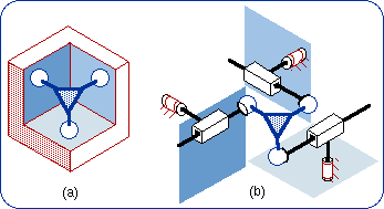
Figure 24: Parallel planar-spherical bonds in a pyramidal device.
The consideration of planar-spherical kinematic bonds leads to a classified gathering of many parallel manipulators, many of which are already known. However the current article has introduced many truly novel parallel mechanisms. The equivalencies, which essentially originate from the product closure in a Lie subgroup of the displacement Lie group are the cornerstone of the employed method. Actually this algebraic approach is a fundamental tool for any mechanism design.
| Bottema, O., and Roth, B., "Theoretical Kinematics," Chapter 4, North-Holland, Armsterdam, 1979. | |
| Hervé, J.M, "The Lie Group of Rigid Body Displacements, a Fundamental Tool for Mechanism Design," Mechanism and Machine Theory, Vol. 34, pp. 719–730, 1999. | |
| Bonev, I.A., Zlatanov, D., and Gosselin, C.M., "Advantages of the Modified Euler Angles in the Design and Control of PKMs," 2002 Parallel Kinematic Machines International Conference (PKS 2002), Chemnitz, Germany, pp. 171–188, April 23–25, 2002. | |
| Lee, K.-M., and Shah, D.K., "Kinematic Analysis of a Three-Degrees-of-Freedom In-Parallel Actuated Manipulator," Proceedings of the International Conference on Robotics and Automation, Raleigh, USA, Vol. 1, pp. 345–350, 1987. | |
| Huynh, P., and Hervé, J.M., "Equivalent Kinematic Chains with Planar-Spherical Bonds Application to the Development of 3-DOF 3-RPS Parallel Mechanism," Proceedings RAAD'03, Cassino, May 7–10, 2003. | |
| Merlet, J.-P., "The Design of MIPS Micro-Robot for Endoscopy Applications," ERCIM News, No. 42, July 2000. | |
| Huang, Z. and Fang, Y.F., "Kinematic Characteristics Analysis of 3-DOF In-Parallel Actuated Pyramid Mechanism, "Mechanism and Machine Theory, Vol. 31, pp. 1009–1018, 1996. | |
| Huang, Z., and Li, Q.C., "Some Novel Minor-Mobility Parallel Mechanisms," Proceedings of the Parallel Kinematics Seminar, Fraunhofer IWU, Chemnitz, pp. 895–905, April 23–25, 2002. | |
| Huang, Z. and Li, Q.C., "On the Type Synthesis of Lower Mobility Parallel Mechanisms," Proceedings of Fundamental Issues and Future Research Directions for Parallel Mechanisms and Manipulators, Quebec City, pp. 272–283, October 3–4, 2002. | |
| Zlatanov, D., and Gosselin, C.M., "A Family of New Parallel Architectures with Four Degrees of Freedom," EJCK, Vol. 1, No. 1, paper 6, 2002. | |
| Karouia, M., and Hervé, J.M., "A Three-DOF Tripod for Generating Spherical Rotation," Advances in Robot Kinematics, pp. 395–402, Kluwer Academic Publishers, 2000. | |
| Karouia, M., and Hervé, J.M., "A Family of Novel Orientational 3-DOF Parallel Robots," RoManSy 14, pp. 359–368, Springer Vienna, 2002. |
| Copyright © 2000– by Ilian Bonev and Jacques M. Hervé | Published on: January 24, 2003 |